078400 - Firestopping
CMU-Firestopping 01 - QN
- Corey S Zussman, AIA
- Link
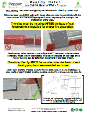
Non-bearing CMU walls will typically be detailed with steel top of wall clips. When we have rated CMU walls with these clips, we need to coordinate with the clip installer and the fire stopping contractors regarding the timing of the installation of the clips.
Spray Fire Proofing 01 Metal Deck - QN
- Corey S Zussman, AIA
- Link
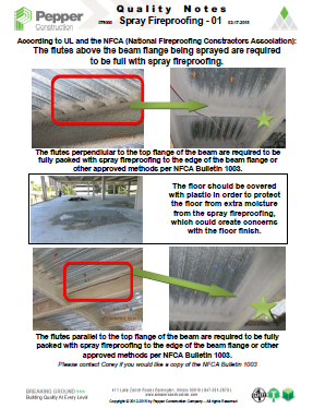
According to UL and the NFCA (National Fireproofing Contractors Association), the flutes above the beam flange being sprayed are required to be full with spray fireproofing.
Spray Fire Proofing 02 Head of Wall - QN
- Corey S Zussman, AIA
- Link
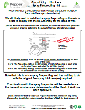
When we install a fire-rated wall directly under and parallel to a spray fireproof beam, we will likely need to install extra spray fireproofing on the web in order to comply with the UL Assembly for the Head of Wall.

Fire Stopping Post-Tensioned Slab Penetration 01 - QN
- Corey S Zussman, AIA
- Link
For post-tensioned concrete slab penetrations, when installing pre-manufactured holes in the slab, we must review the entire hole that is created in the slab, make sure that it falls completely within the stud framing (not the drywall).

Fire Stopping 01 Penetrations - QN
- Corey S Zussman, AIA
- Link
When we have a rated partition, we should not be taping the drywall to the penetrating item, such as electrical, water, insulated pipes. This is not an acceptable UL Assembly for the penetration.
Fire Stopping 02 Precast Plank - QN
- Corey S Zussman, AIA
- Link
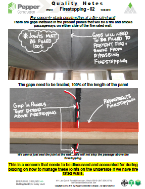
For concrete plank construction at a fire rated wall, there are gaps installed in the precast planks that will be a fire and smoke passageways on either side of the fire rated wall. The gaps need to be treated, 100% of the length of the panel.
Fire or Acoustical Pads - Issue 24
- Corey S Zussman, AIA
- Link
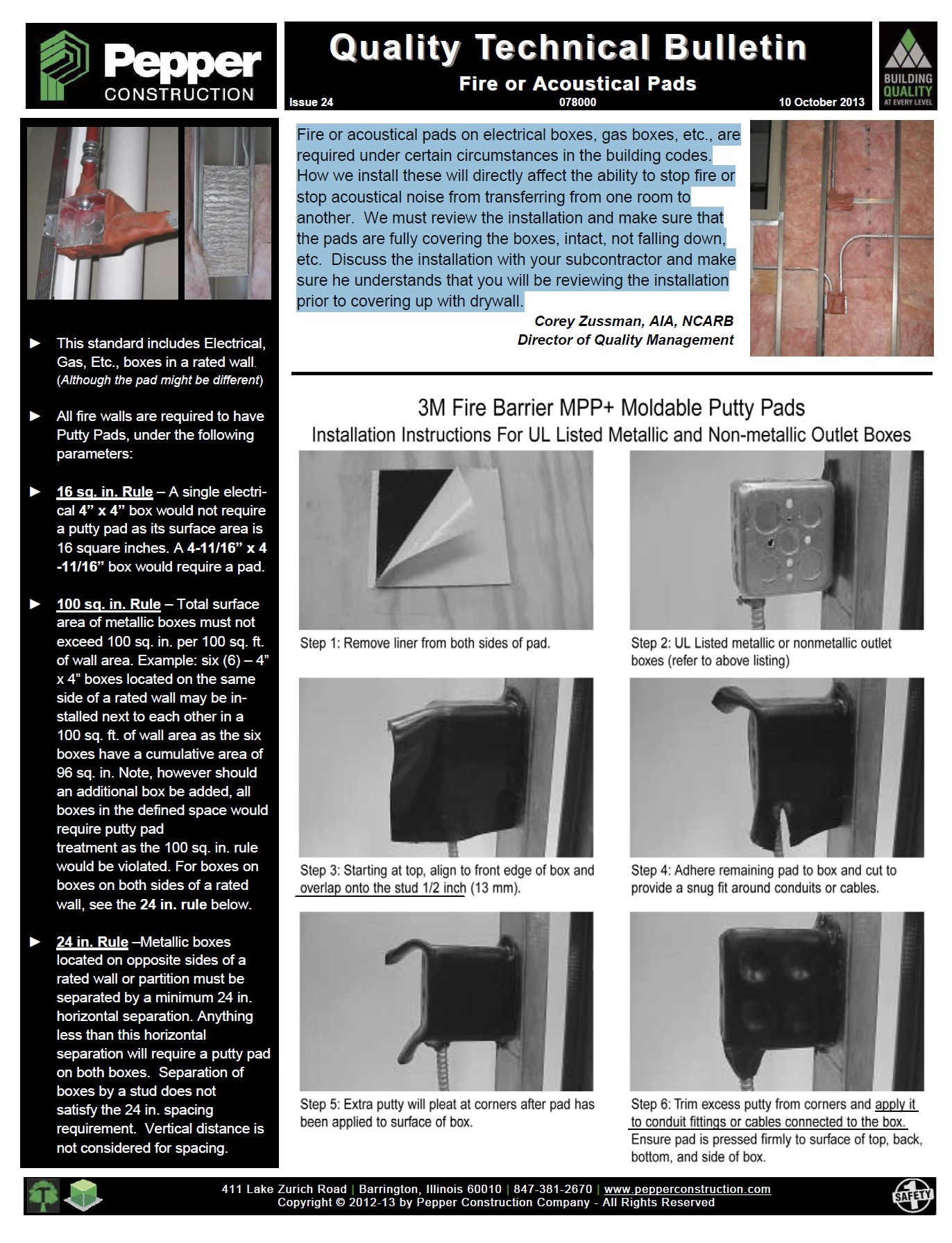
Fire or acoustical pads on electrical boxes, gas boxes, etc., are required under certain circumstances in the building codes. How we install these will directly affect the ability to stop fire or stop acoustical noise from transferring from one room to another. We must review the installation and make sure thatthe pads are fully covering the boxes, intact, not falling down, etc. Discuss the installation with your subcontractor and make sure he understands that you will be reviewing the installation prior to covering up with drywall.
Head of Wall Part 1 - Fire Stop Joint - Issue 13
- Corey S Zussman, AIA
- Link
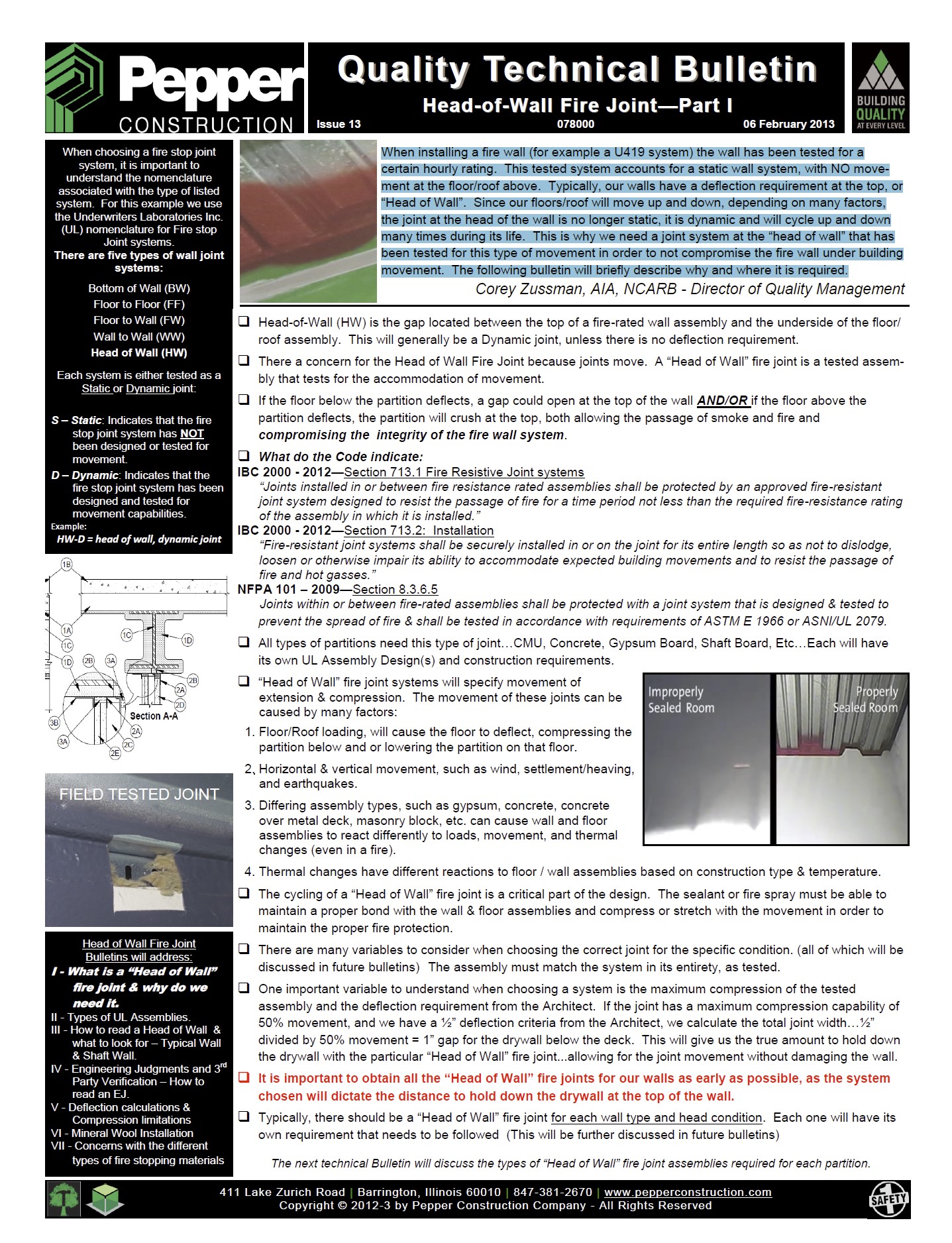
When installing a fire wall (for example a U419 system) the wall has been tested for a certain hourly rating. This tested system accounts for a static wall system, with NO move-ment at the floor/roof above. Typically, our walls have a deflection requirement at the top, or “Head of Wall”. Since our floors/roof will move up and down, depending on many factors, the joint at the head of the wall is no longer static, it is dynamic and will cycle up and down many times during its life. This is why we need a joint system at the “head of wall” that has been tested for this type of movement in order to not compromise the fire wall under building movement. The following bulletin will briefly describe why and where it is required.
Head of Wall Part 2 - Different Conditions - Issue 14
- Corey S Zussman, AIA
- Link
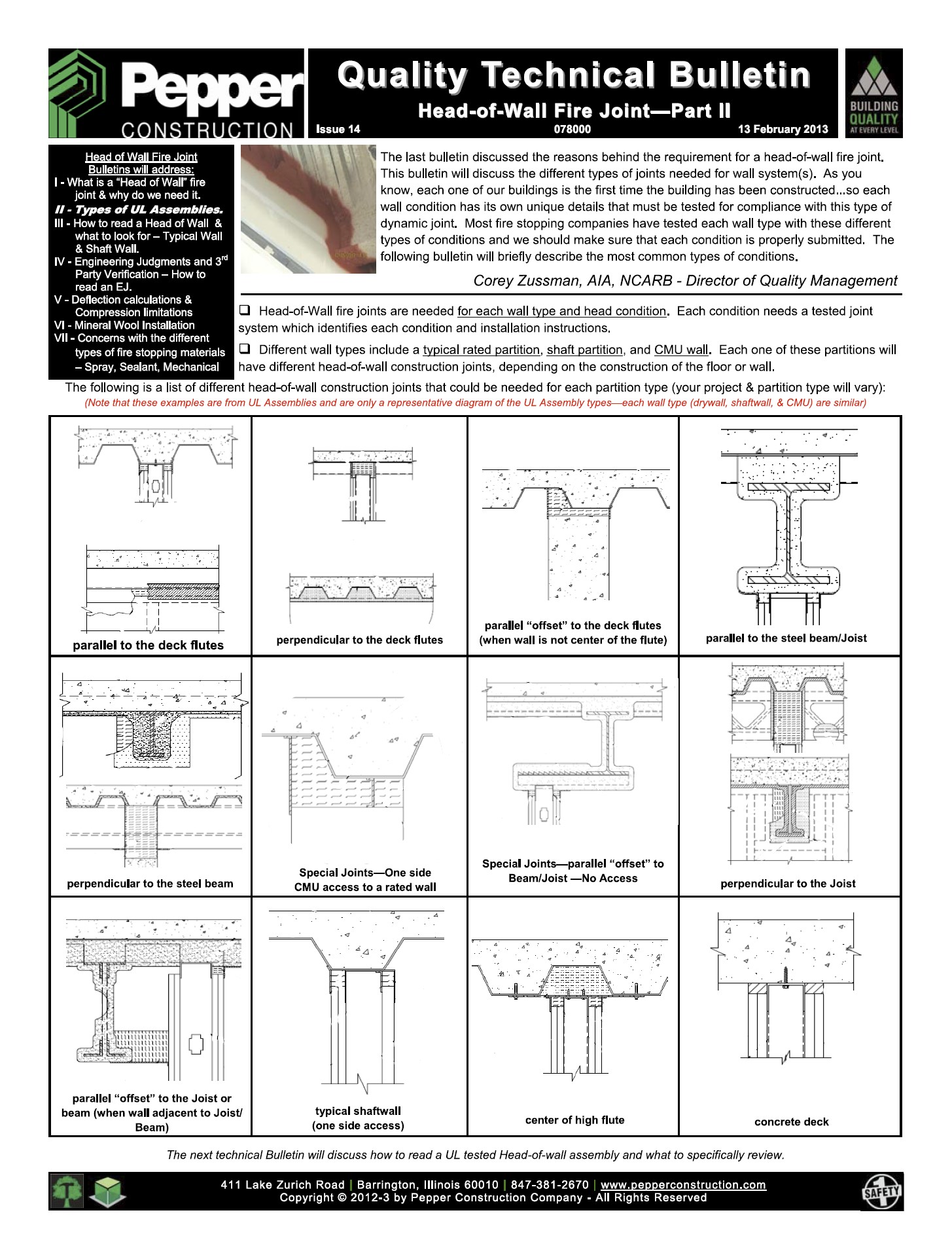
The last bulletin discussed the reasons behind the requirement for a head-of-wall fire joint. This bulletin will discuss the different types of joints needed for wall system(s). As you know, each one of our buildings is the first time the building has been constructed...so each wall condition has it's own unique details that must be tested for compliance with this type of dynamic joint. Most fire stopping companies have tested each wall type with these different types of conditions and we should make sure that each condition is properly submitted. The following bulletin will briefly describe the most common types of conditions.
Head of Wall Part 3 - Read UL Report - Issue 15
- Corey S Zussman, AIA
- Link
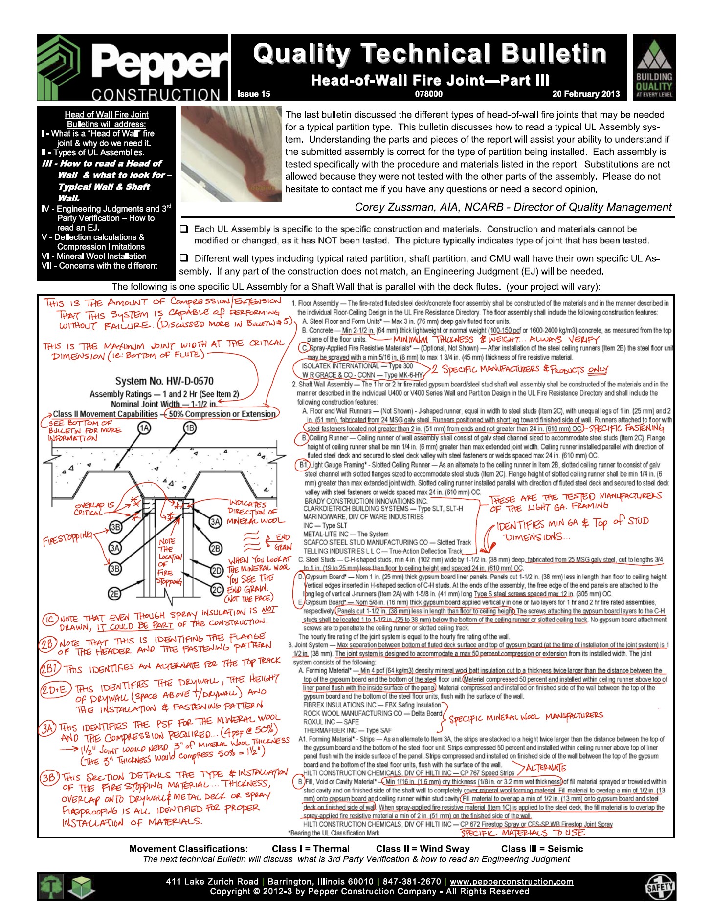
The last bulletin discussed the different types of head-of-wall fire joints that may be needed for a typical partition type. This bulletin discusses how to read a typical UL Assembly system. Understanding the parts and pieces of the report will assist your ability to understand if the submitted assembly is correct for the type of partition being installed. Each assembly is tested specifically with the procedure and materials listed in the report. Substitutions are not allowed because they were not tested with the other parts of the assembly. Please do not hesitate to contact me if you have any questions or need a second opinion.
Head of Wall Part 4 - Engineers Judgment - Issue 16
- Corey S Zussman, AIA
- Link
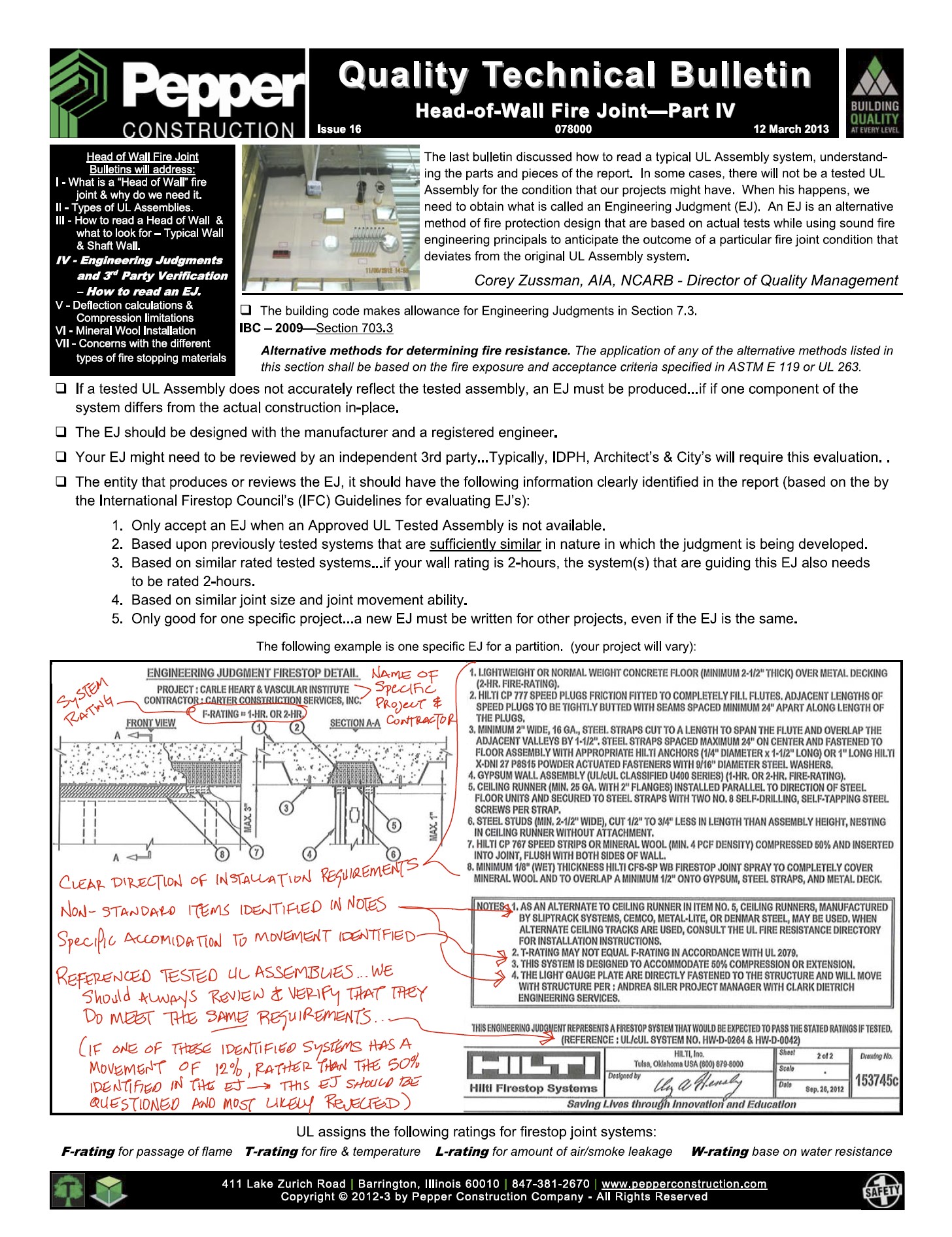
The last bulletin discussed how to read a typical UL Assembly system, understanding the parts and pieces of the report. In some cases, there will not be a tested UL Assembly for the condition that our projects might have. When this happens, we need to obtain what is called an Engineering Judgement (EJ). An EJ is an alternative method of fire protection design that are based on actual tests while using sound fire engineering principals to anticipate the outcome of a particular fire joint condition that deviates from the original UL Assembly system.
Head of Wall Part 5 - Deflection and Compression - Issue 17
- Corey S Zussman, AIA
- Link
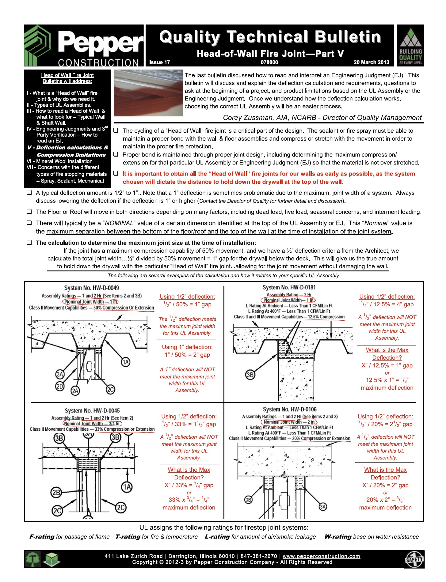
The last bulletin discussed how to read and interpret an Engineering Judgement (EJ). This bulletin will discuss and explain the deflection calculation and requirements, questions to ask at the beginning of a project, and product limitations based on the UL Assembly or Engineering Judgement. Once we understand how the deflection calculation works, choosing the correct UL Assembly will be and easier process.
Head of Wall Part 6 - Mineral Wool - Issue 18
- Corey S Zussman, AIA
- Link
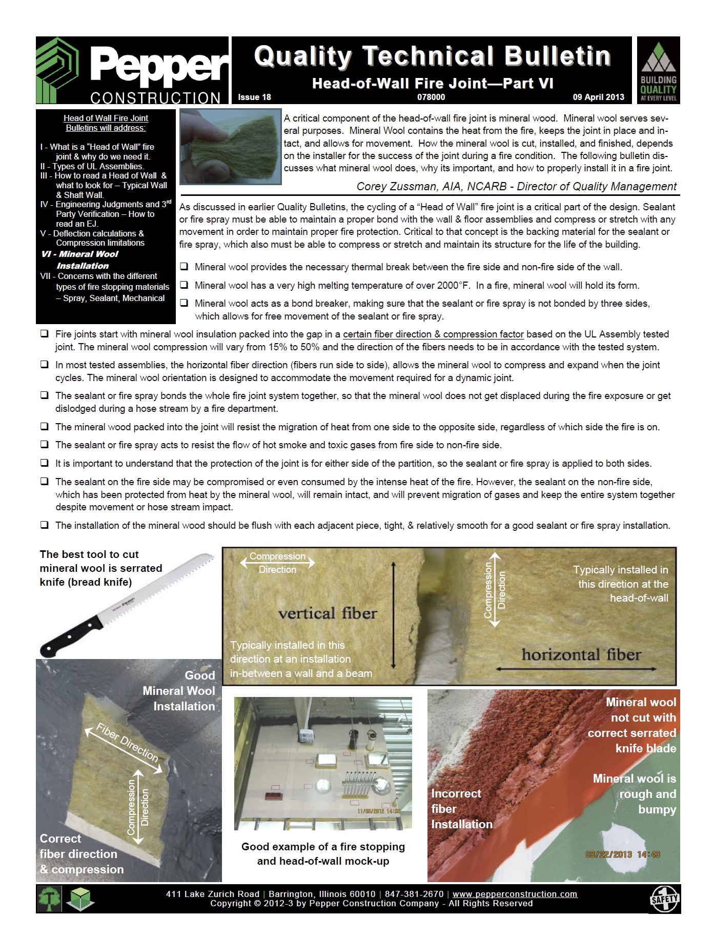
A critical component of the head-of-wall fire joint is mineral wood. Mineral wool serves several purposes. Mineral Wool contains the heat from the fire, keeps the joint in place and intact,and allows for movement. How the mineral wool is cut, installed, and finished, depends on the installer for the success of the joint during a fire condition. The following bulletin discusses what mineral wool does, why its important, and how to properly install it in a fire joint.
Head of Wall Part 7 - Material Types - Issue 19
- Corey S Zussman, AIA
- Link
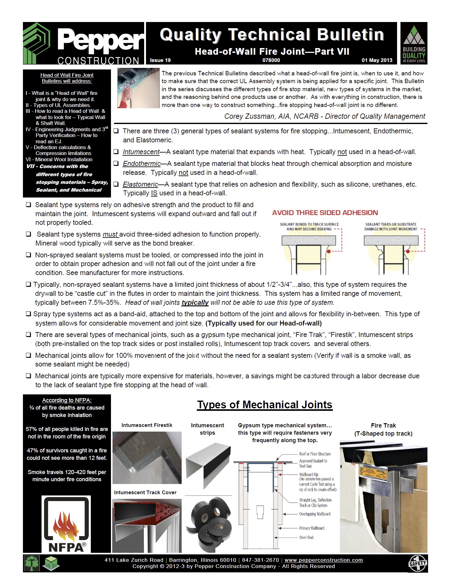
The previous Technical Bulletins described what a head-of-wall fire joint is, when to use it, and how to make sure that the correct UL Assembly system is being applied for a specific joint. This Bulletin in the series discusses the different types of fire stop material, new types of systems in the market, and the reasoning behind one products use or another. As with everything in construction, there is more than one way to construct something...fire stopping head-of-wall joint is no different.
Head of Wall 01 Overspray - QN
- Corey S Zussman, AIA
- Link
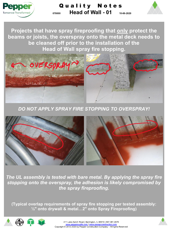
Projects that have spray fireproofing that only protect the beams or joists, the overspray onto the metal deck needs to be cleaned off prior to the installation of the Head of Wall spray fire stopping.
Fire Stopping 03 Supported Penetrations - QN
- Corey S Zussman, AIA
- Link
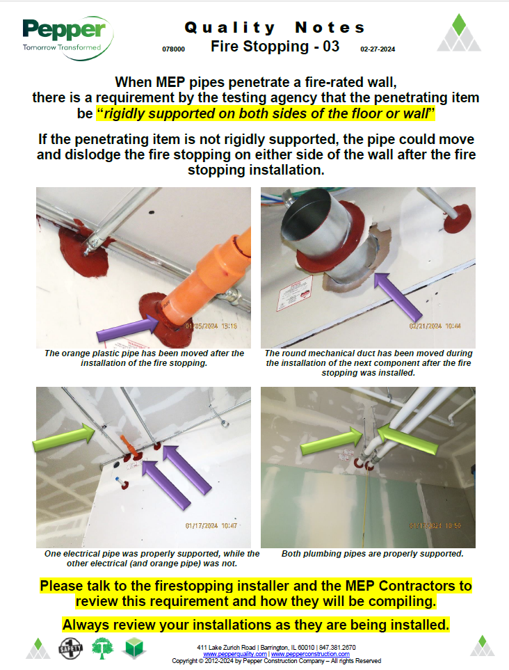
When MEP pipes penetrate a fire-rated wall, there is a requirement by the testing agency that the penetrating item be “rigidly supported on both sides of the floor or wall”. If the penetrating item is not rigidly supported, the pipe could move and dislodge the fire stopping on either side of the wall after the fire stopping installation.

Existing Fire Rated Hole Plug 01 - QN
- Corey S Zussman, AIA
- Link
Dealing with existing holes in rated and non-rated concrete floor decks. When we do remodels, we typically find existing penetrations with-in the wall cavity, which will need to be filled somehow, typically by going underneath and covering the hole and going back up and filling the core with concrete. With this type of install, and we typically have flooring damage due to shrinkage of the fill, and most likely a fill that is not rated. CorPlug is a product that the Quality Department found last year that allows for the filling of the core from the topside and is a tested assembly for up to 2-hours.
Precast Concrete and Interior Wall - Lateral Deflection QN
- Corey S Zussman, AIA
- Link
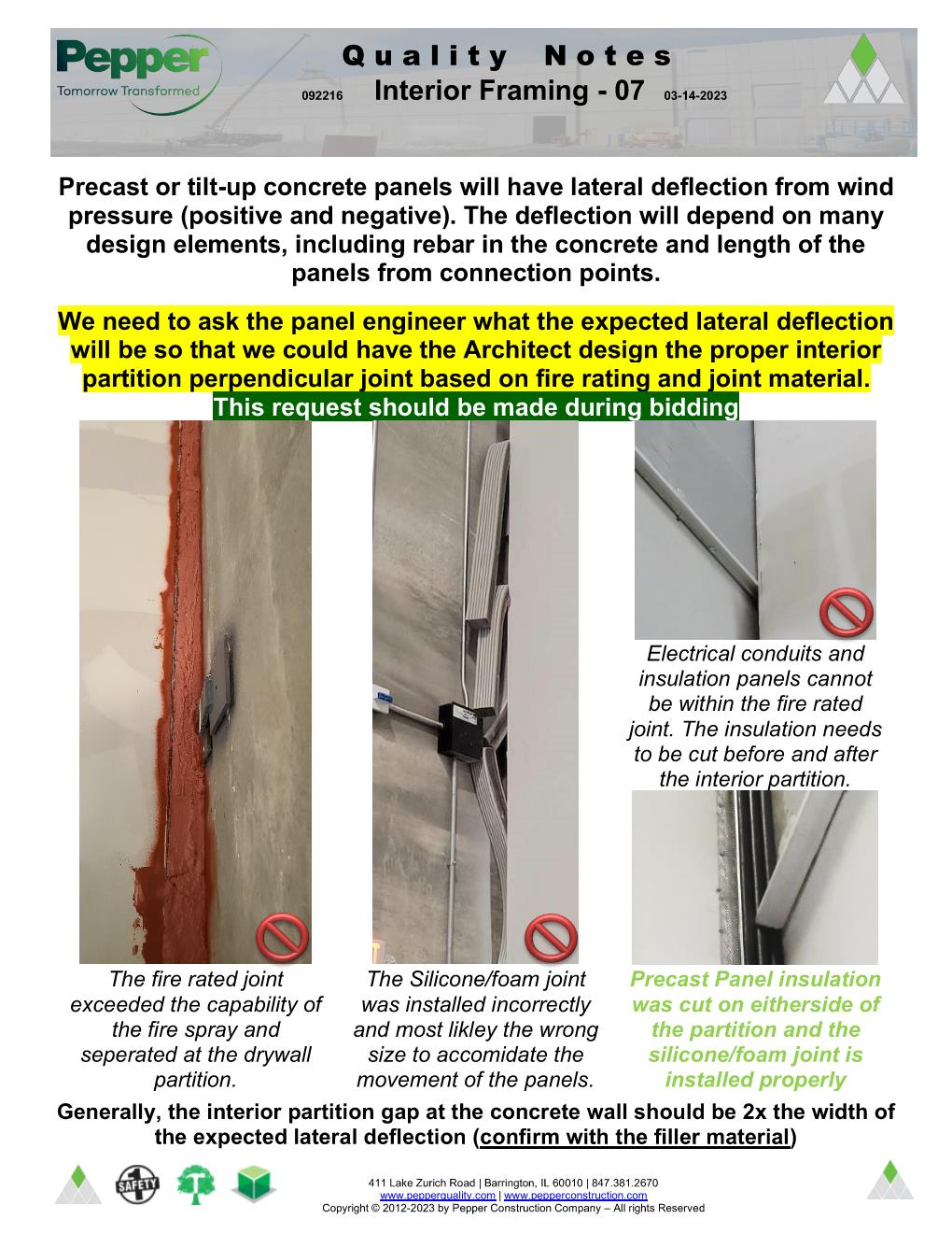
Precast or tilt-up concrete panels will have lateral deflection from wind pressure (positive and negative). The deflection will depend on many design elements, including rebar in the concrete and length of the panels from connection points. We need to ask the panel engineer what the expected lateral deflection will be so that we could have the Architect design the proper interior partition perpendicular joint based on fire rating and joint material. This request should be made during bidding

Pepper Quality Application is a web-based software solutions help to manage, track and report construction projects.
Quality Resources
Administrator/Reviewer Links
Project Managers
2016 © Dang Do - Pepper Construction. All Rights Reserved. Privacy Policy | Terms of Service